During my teens, I've always desired the Tamiya Hotshot. It was the first 4WD buggy to be released at a time when many were simply 2WD. Unfortunately due to very limited pocket money at that stage in my life, that just remained a dream.
Now fast forward about 30 years into the future, when I learned that Tamiya decided to re-release the Hotshot again, I may now have a chance to make that teenage dream come true.
Acknowledgements:
My supportive wife - without her help, I won't have the time to pursue this.
Eugene - my old friend who helped purchased & delivered it to my parents
My parents - who carried it safely from singapore back to perth
Mike - my colleague who helped with the painting of the finer parts
Official specs link:
http://www.tamiya.com/english/products/58391hotshot/
Further helpful info link:
http://www.ultimatetamiya.com/buggies/hot-shot-re/
http://tamiyablog.com/2007/07/a-quick-review-of-hotshot-2007-based-on-manual-updated-july-24th/
Before starting, it's always a good idea to lay out all the parts & identify the various sections
And also a toolbox to organize and neatly store away all the little screws, nuts & bolts.

And to ensure the finished parts are smooth, there's going to be lots of filing away of the little bits of plastic. Unfortunately I find this to be the most time consuming part of the build.

Rear gearbox with motor attached

Front gearbox

Front and Rear gearboxes placed side by side

Rear gearbox prior to suspension attachment

Upper arm suspension attached

Lower arm suspension attached to the rear gearbox and that concludes step 11 of 47 (36 more to go...)

Step 12 - Layout the front uprights

Completed! They were quite fiddly


L/R upper & lower arms attached to the uprights prior to attaching the front gearbox

Step 14 completed! - suspension is now integrated with the front gearbox

Step 15 - Let's take a break - with some minor painting!

Digressing from the build, I'll provide some info on this upgraded component. The item is the Ball Bearing Set - Tamiya product code 54002

The pack contains a total of 18 ball bearings which replaces the following:
Instruction manual code MS1 (13x plastic bearings);
Instruction manual code MR3 (5x metal bearings).
I don't know why Tamiya chose to issue the inferior plastic & metal bearing in the 2007 re-release? Why not just issue the upgraded ball bearing set as standard issue?
Anyways, the re-re Super Hotshot (the pinnacle of the 'shot' series) includes the upgraded ball bearing set as standard issue.
Another very useful tool which I've got recently is the Basic Tool Set - Tamiya product code 74016.

The tool set includes a side cutter which has almost eliminated my time filing away at the plastic bits. Previously it was very time consuming as the bits were a residue of my using a standard scissors to cut off the parts. Now with using the new side cutter, the cut is very clean and no residual bits left to file. Highly recommended!
For the stock 'Mabuchi RS 540SH Motor' I'll be using the supplied 13T pinion gear. Its gear ratio is 10.043:1
which i reckon equates to very high acceleration, but low top end speed.
Next up will be the supplied 15T pinion gear. Gear ratio 8.704:1
probably slower acceleration, but higher top end speed.
the manual made mentioned of 2 other pinion gears but did not supply them:
16T pinion gear - gear ratio 8.160:1
17T pinion gear - gear ratio 7.680:1
The recommended tune-up motor is the 'Dirt-Tuned Motor 27T' - Tamiya product code 53929
Makes me wonder if the 27T motor is actually compatible with the above said 17T pinion gear?
Maybe a question for another time... ?

For now I'm happy just to pair the stock motor with the lowest 13T gear. I won't be partaking in any competition endurance race anytime soon.
ok siesta time's over, let's get back to painting. Since I needed to paint the colour black, I painted all the black sections at 1 go. My painting efforts are pretty amateurish when compared to the figurehead done by Mike, my colleague aka 'modeller extraordinaire'

A close up shot of the figurehead. Mike even did the dust on his cheeks. How professional is that! Thanks Mike! :-)

While waiting for the enamel paint to dry, I moved on to Step 17 - the rear suspension crank

Step 18 requires 3 major parts to be put together to the rear gearbox. Firstly, the stabilizer rod needs to be secured by part E5.

Secure both ends of the stabilizer rod. Rear stabilizer done!

Next part - attaching the rear suspension crank

Lastly, attaching the chassis thus completing Step 18 of 47

These 2 screws are critical because they are holding the chassis & the rear gearbox together.

Rear view of the suspension crank, double wishbone suspension & stabilizer. Absolutely love how everything connects to each other.

Alert! - the stickers on the large sheet are not water-activated decals, they need to be cut as close to the outlines as possible. The smaller cut ones @ the top right corner are water-activated decals.

Step 19 attaching the front gearbox and inserting the main propeller shaft - the heart of the 4-Wheel Drive train! Tip - it's better to fix the figurehead after completing step 19. Trying to balance the whole thing on the rounded figurehead is quite an effort.

Flipped right side up.

View from another angle. Getting excited now. But according to the instruction manual, my progress hasn't even reached the 50% mark. 28 more steps to go... oh well...

Step 20 - Damper cylinder assembly

one end done

laying the other end out

almost done... my goodness, a simple shock absorber piston requires 9 little interior parts (not including the cap)

all done! for all the trouble, at least there's a quality feel to it!

Step 21 - filling the piston cylinders with real oil. The supplied oil is the 'hard set - light blue' type. No mess, was quite glad I didn't spill a single drop of oil!
Was quite curious how I could slowly move the piston up & down without the oil overflowing from the cylinder. Only then I realised that part 'W5' has 2 holes which allow the oil to flow through to the other side thus compensating for the difference in the pressures.

Step 22 - time to encase the aluminium cylinder in red plastic & coil spring. Be careful to move rubber o-ring away from part 'BD2' before gripping it with the long nose pliers. I lost an o-ring because of it. The coil spring under tension requires quite a bit of hand muscle.

Step 22 completed! I wonder what does T.S.A.D stand for? Too Sad Already Done?
Indeed I was sad I lost an o-ring...

ok. time to move on...
Step 23 attaching the front stabilizer

next... attaching front shock absorber - done!

Step 24 of 47 prior to attaching the rear shock absorber

rear shock absorber done! you can see from the bend in it that it's under tension.

View from the opposite direction

Top down view

Front view

Rear view

I've reached about 50% mark of the build.
Next stage will be the electrics.
Step 25 - Charging the battery pack
Eugene, thanks for your charger

Step 26 - Laying out all the radio control gear
R/C: Futaba 3PRKA (3-channel, FHSS)
Receiver: R203GF
Servo: S3003
ESC: Tamiya TBLE-02S

Steps 27, 28 & 29
Quite tricky here.
Needs some hand muscle to hold the small red part steady when securing to the servo
But I do like how there are little internal red parts in keeping with the red theme of the car

Next is dropping in the ESC & Receiver. Quite a tight fit.
Hard to imagine how they could still squeeze in a mechanical speed controller back in 1985.

Another zoom out pic of it

Step 31 - prior to attaching the front bumper and skid plate

Step 31 - completed! skid plate protects the servo saver & steering rods where it would otherwise be vulnerable.

Step 33, 34 - assembling the roll bar frame which includes the netting & roof

how it looks like prior to attachment to chassis

Now securely attached to chassis. I absolutely love the retro look of this. It's what defines the buggy profile. Call it 'old school' but modern buggies just can't cut it for me.

side view

side view (motor)

Step 35, 36 - Heat sink feature. Due to the use of a mechanical speed controller, ceramic heat sinks were required back in 1985

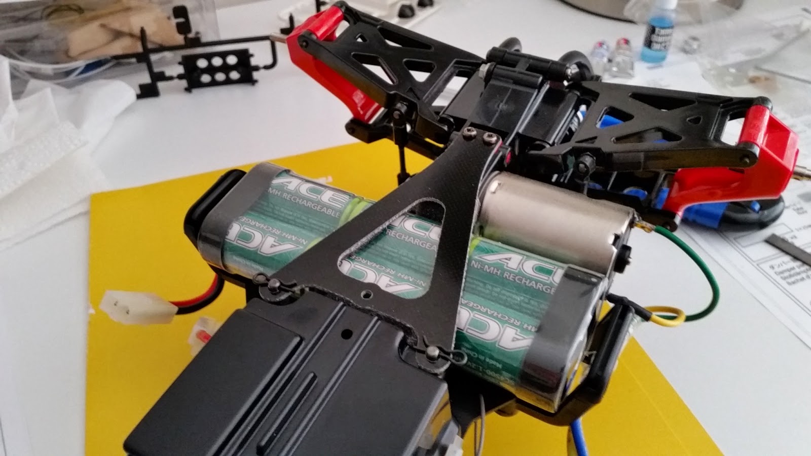
Step 37, 40 - Battery plate attached.
Step 38 - Wheels & Tyres. Note: the tyres are directional.

Step 39 - I opted to go with plastic antenna pipe instead of the stiff metal antenna.

This basically concludes the build. Now I just need to get the body painted & stickers applied.
Will add more pics later.


How the shell looks after the paint has dried

once the exterior film is peeled away, reveals a very glossy finish!

Here it is - all finished!


Answer to that question - Yes definitely!


Thanks for visiting my blog :-)